
Notice
Recent Posts
Recent Comments
Link
- 네이버 오디오필 카페
- 네이버 하이디오 보청기 카페
- -
- OPM3320D
- OPM3320S
- OPM2320D
- OPM2320S
- OPM401 (DUAL)
- OPM402 (SINGLE)
- OPM2401 (DUAL)
- OPM2402 (SINGLE)
- OPA301 (DUAL)
- OPA302 (SINGLE)
- OPA2301 (DUAL)
- OPA2302 (SINGLE)
- OPM306 (DUAL)
- OPM307 (SINGLE)
- OPM316 (DUAL)
- OPM317 (SINGLE)
- OPM3402 (Single)
- OPM3401 (Dual)
- OPA3302 (Single)
- OPA3301 (Dual)
- 오디오필 카페
| 일 | 월 | 화 | 수 | 목 | 금 | 토 |
|---|---|---|---|---|---|---|
| 1 | 2 | 3 | 4 | |||
| 5 | 6 | 7 | 8 | 9 | 10 | 11 |
| 12 | 13 | 14 | 15 | 16 | 17 | 18 |
| 19 | 20 | 21 | 22 | 23 | 24 | 25 |
| 26 | 27 | 28 | 29 | 30 | 31 |
Tags
- 고음질
- opm3320d
- ms15a
- 증폭기
- 오디오 메인보드
- CCDT
- opm2320s
- 슬롯오디오
- 진공관
- 디스크리트 오피앰프
- opm2320
- 하이파이
- AudioFeel
- HD2265
- 하이엔드
- 메인보드 공개
- 게르마늄
- opa301
- opm320
- opm3320s
- opm2320d
- 조립오디오
- 반도체
- 오디오필
- 어샘블리오디오
- discrete op amp
- 오디오
- 메인보드
- opm3320
- HI-FI
Archives
- Today
- Total
오디오필 음향연구소 (AudioFeel) ~ 인류를 즐겁게… ~
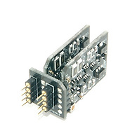
OPM401 MK2s DUAL Offset Adj AUDIOFEEL DISCRETE OP-AMP, Same as a OPA301 본문
제품 - EN
OPM401 MK2s DUAL Offset Adj AUDIOFEEL DISCRETE OP-AMP, Same as a OPA301
오디좋아 2018. 2. 10. 14:59DISCRETE LOW-NOISE OPERATIONAL AMPLIFIERS
OPM401 MK2s (DUAL): Low Impedance , (Board design change)
(OPA301 + Offset adjustment)
Same as OPA301


FEATURES
Additional offset adjustment and offset stabilization *****
Better in low impedance circuit *****
High-Quality Audio-Grade Operational Amplifiers
Composed of High-performance Discrete Components
JFET use High Input Impedance
Excellent effect at Low Impedance Circuit as a Driving Force in afford
Dip 8 Pin Compatible with the general Op Amp
Clean and Crisp, Rich and Non-Irritating and Relaxing Signal Output
Buffer amplifier (gain = 1) : OPM2401 or OPM2402 are recommended.
Active low pass filter : Available without restrictions
APPLICATIONS
Hi-End Audio Pre-Amplifiers
Active-Filter
Differential Current Mode Op-Amp Circuit for Active-Filter
(Example: Active Filter for ES9018)
Professional Audio
TECHNOLOGY APPLIED
Small Signal Buffer Amplification Circuit
Absolute Current Limit, Overcurrent Limiting Circuit
Electronic Circuits for Preventing Floating
ABSOLUTE MAXIMUM RATINGS
Supply Voltage(VS) : ±18V or +36V
Input Voltage : ±Vs
Differential Input Voltage : ±0.7V
Output impedance : 0.38 ohm
Output Current
Internal Current Limit (1) : ±120mA
Allow the average current Vs = ±5V : ±90mA
Allow the average current Vs = ±10V : ±50mA
Allow the average current Vs = ±15V : ±30mA
Storage Temperature Range ; -40°C to +120°C
Operating Temperature Range : -20°C to +70°C
SPECIFICATIONS
Input offset voltage : <±0.5mV (@ VS = ±4.5 to ±18V)
Slew Rate : 51 V/uS (7V, G=x1, RL= 600 Ω)
OPEN-LOOP GAIN : 68dB (VO = ±10V, RL = 600 ohm)
Gain-Bandwidth Product : 11Mhz (@ G = 2)
Output Voltage Swing (RLOAD = 600 Ω), Vrms (Vdc)
Vs = ±5V : 2.6 (±3.6V)
Vs = ±10V : 6.1 (±8.6V)
Vs = ±15V : 9.6 (±13.7V)
Quiescent Current (2)
Vs = ±5V : 48mA
Vs = ±10V : 52mA
Vs = ±15V : 56mA
Dimensions : 25(W) x 44(H) x 17(D) mm
Notes:
(1) +Vs and GND between or between -Vs and GND, The power supply voltage(Vs) is below ±5V, 5 seconds or less condition.
(2) In the power circuit, Quiescent Current(Power Current) must be designed to be a fully supplied. Should be used on circuits that can supply enough Quiescent Current(Power Current).
Use this product under the following conditions:
* In OPAMP circuit, "the final gain" is equal to or less than the x10 (+ 20dB). (Active filter, buffer, etc.)
* Do not use as a buffer amplifier (gain = 1), Final Gain will use more than x1.5 (+3.5dB). But, it can be used as an opamp in the active filter. (low-pass filter)
* The length of the Extension DIP8 should be as short as possible.
HOW TO CHOOSE THE OPM401(or OPM402) AND OPM2401(or OPM2402)
OPM401(or OPM402) and OPM2401(or OPM2402) are selected according to an opamp circuit impedance values.
1. OPM401(or OPM402): Use for the low impedance circuit
Feedback-Resistor is less than 1000 ohm
Headphone-Amp output circuit (only if the supply voltage is ± 5V or less)
However, due to high Supply Current (Quiescent Current), depending on the product, you need to check it even if the Supply Voltage is reduced.
2. OPA3301(or OPA3302): Use for a Medium impedance circuit
Feedback-Resistor is Between 1000 ohm and 5000 ohm
However, the Supply Current (Quiescent Current) is Medium.
3. OPA2301(or OPA2302): Use for a high impedance circuit
Feedback-Resistor is more than 5000 ohm
However, the Supply Current (Quiescent Current) is low.
4. If you do not know the value of the Feedback-Resistor or uncertain, the two, it is recommended that you choose to try the actual use.
Feedback Resistor is:
Resistor connected between the Negative Input and Out in opamp circuit.
*********************************************************************************************************************************************************
Notice - Ideas to Maintain Performance of Discrete Operational Amplifiers
We will show you ideas for keeping the discrete op amp (OPA301, OPM401 ... etc) at maximum performance.
Our discrete op amp features delicate, rich and powerful sound.
We've been working on a variety of new technologies to make sure you get a very satisfying sound.
The components used in the discrete op amp are equipped with precision and delicate high-performance components.
Performance of this type of discrete op amp can change depending on the environment.
Check that the discrete op amp you are using meets the following specifications.
1. Is there foreign material on the surface of the discrete op amp? (There is also invisible pollution, conductive materials, etc.)
2. Is the surface of the discrete op amp exposed to moisture?
3. Is the surface of the discrete op amp exposed to smoke or gas?
4. Is the discrete op amp used for a long time?
5. Do you feel that the performance of the sound is lacking?
For the above reasons, the surface of the discrete op amp may be contaminated,
As a result, the performance of the sound may be insufficient.
To maintain the best performance of the discrete op amp;
Periodically check the status of the discrete op amp,
It is a good idea to clean the discrete op amp.
We recommend that you periodically clean the discrete op amp.
A method for cleaning a discrete operational amplifier;
1. Spray spray cleaner for electronic circuit board. (See how to use the cleaning agent)
2. Clean the environmentally cleaner with a brush. (See how to use the cleaning agent)
3. Immerse in washing solution of ultrasonic washing machine. (See how to use the cleaning agent)
(Note) If you feel that the newly purchased Discrete Op Amp is lacking in performance, clean it.
You can remove contamination that occurs during transportation.
AUDIOFEEL's technology to improve the cool, thin and dry sound characteristics of silicon transistors
Amplifiers, usually made of transistors, are rated to be cool, thin and dry. To improve this tendency, we add a little capacitor to adjust the sound propensity. As a result of this tuning process, a part of the treble is cut and the feeling of opening is reduced.
So it is very difficult to hear the actual sound being played in a transistor amplifier.
AUDIOFEEL has the technology to solve the disadvantages of these transistors and it is applied to all the products that we produce now. Just like a tube amp, it is warm, gentle, clear and transparent, and all sounds are independently distinguished, full of emotion and power.
How was the technology that complements the disadvantages of silicon transistors implemented?
The principle is simple. The key is to configure the circuit so that current silicon transistors behave like germanium transistors.
"The germanium transistor has a leakage current between the collector and the base." This condition applies to the silicon transistor circuit.
In Figure 21 below, transistor (A21) is a block representing one silicon transistor. The load (CCL21) is a block that represents a resistive load or a constant current load. This is a simple representation of the transistor 1 stage amplifier.
Silicon transistors do not have any leakage current between collector (C) and emitter (E).
In other words, a silicon transistor amplifier consisting of only A21 and CCL21 is cold, thin and dry.

To use a silicon transistor amplifier consisting of A21 and CCL21 in Figure 21 as a germanium transistor amplifier, connect the constant current source NCC22 for leakage current in parallel with A21.
Then, leakage current flows through the NCC22 between the collector and emitter of the silicon transistor, and the silicon transistor A21 behaves as if the leakage current is always flowing. As a result, this amplifier behaves like a germanium transistor.
NCC21 is required to always supply current to NCC22.
Connect NCC21 and NCC22 (red box display) circuit for leakage current to the collector and emitter of the silicon transistor in parallel. As a result, despite the use of silicon transistors, it is warm, gentle, clear and transparent as the sound of a tube, and all sounds are independently distinguished, full of emotion and power. It also has the advantage of being less influenced by electromagnetic waves and external noise.
(details)
Let's take a look at the AUDIOFEEL technology, which improves the cool, thin and dry characteristics of silicon transistors.
Long ago, vacuum tube radios were produced, followed by germanium transistor radios, and then silicon transistor radios.
?Germanium transistor radio sound was good.
Silicon transistor radio, however, has the power to sound, but it is cold, thin and dry.
The problem with silicon transistors has not been improved to this day.
So what is the difference between a germanium transistor and a silicon transistor?
The answer lies in the difference in insulation characteristics or insulation between electrodes.
Indicated by Icbo in the transistor specification table.
The leakage current Icbo between the collector and base of the germanium transistor is 8uA ~ 30uA. (AC124, AC125, etc.)
On the other hand, the leakage current Icbo between the collector and base of the silicon transistor is 0.1 uA max. It is about 100 times more different.
Accurately, it is accurate to compare the leakage current Iceo between the collector and the emitter, but the transistor datasheet does not display Iceo well, so we compared it with Icbo.
The leakage current between the collector and the emitter shows that the silicon transistor is much smaller than the germanium transistor and the isolation is better.
Since there is always electrons in the vacuum tube, a fine current flows from the plate to the cathode even at the cutoff, and it is the same as the germanium transistor that the plate current is not blocked.
The FET also has a fine current flow from the drain to the source at the cutoff, and it is the same as the germanium transistor that the drain current is not blocked.
However, because of the high isolation characteristics of silicon transistors, there is a moment when collector current is cut off during cutoff. Therefore, there is a lack of sound quality in the use as an acoustic amplifier.
So why is the insulation characteristic of a silicon transistor a problem?
It takes some time until the change of the input signal coming to the base from the amplification circuit composed of transistors is outputted to the collector.
If the input signal voltage applied to the base decreases, the collector current decreases, the collector impedance increases, the moment the load resistance and collector electrodes separate, and the potential of the load resistance becomes a floating state.
At this time, the germanium transistor maintains the connection state with the load resistance because the leakage current always flows. However, since the insulation of the silicon transistor is too good, the collector current is completely cut off and separated from the load resistance. Or is easily exposed to ambient noise or electromagnetic waves. That is, the amplified signal is easily deformed.
Silicon transistors have a very good isolation between the collector and the emitter, so there is a moment when the collector and the load resistor are cut off during the amplification and the potential of the load resistor is floating. At the moment of this float, the voltage is changed to a completely different voltage than the amplified signal, and is easily affected by the ambient noise and changed to a different voltage than the amplified signal.
That is, the amplified output signal is distorted.
If it is deformed by a pulse voltage, it becomes a stimulating sound. Also, it does not follow gentle low-band signal level and can not reproduce the sound of deep bass.
In today's world, transistors are all silicon transistors, and germanium transistors are rarely produced or used. Both low-end audio and high-end audio are made of silicon transistors, if not vacuum tubes.

'제품 - EN' 카테고리의 다른 글
'제품 - EN' Related Articles
more


Comments